

Free Energy
Green Energy
Levitating Roof Top Windmill
Wind Power
G. Allan Oram
ENGINEERING SUSTAINABILITY
Construction code mandates each building have sufficient ventilation systems. Thus, many different ventilation designs are in existence. One design incorporates a rotating vent cap turbine atop a mounting fixture. These turbines are designed to trap convection currents and assist evacuation of structures' ventilation systems. At present, many buildings around the world incorporate these vent cap turbines for ventilation purposes, and some buildings have multiple turbines sitting atop them. In this report, we discuss costs and procedures Energy Consultation and Materials Design, (Energy Con) made to convert rotating vent cap turbines into electricity producing 'power' windmills, without disturbing the vent cap turbine's intended ventilation purposes.
Abstract
We have created novel permanent magnetic levitation bearings, and have eliminated the conventional gearbox to gain more power output from vertical axis wind turbine, (VAWT) technology. We've done this through magnetic suspension that creates very little friction between rotor and stator assemblies, and have inhibited inefficient start-up problems in current vertical windmill technology. A major breakthrough was observed in our initial testing environment. Diagnostic instruments have shown us that this novel system appears to be generating power even while the rotator remains stationary. As this is a direct violation to the First Law of Thermodynamics, if this is occurring, we believe this system is somehow converting the energies stored in the stationary magnets' toroidal spheres. Energy that was produced by the geomagnetic core of the Earth, and sequestered in permenant magnets. More information is needed before any real conclusions can be attained.
Implications
ECMD Energy's windmill project focused on cutting-edge technology. Addressing the known Laws of Thermodynamics, Energy Con initially began trying to gain windmill efficiency by minimizing friction and mechanical losses in traditional, gearbox, bearing and shaft assemblies. We did this by using opposing forces found in permanent magnets. These toroidal spheres, coupled together, act as a levitation bearing between the rotor installed into the bottom of the rotating vent turbine, and the stator installed in the vent cap's mounting conduit. With a robust high-heat dissipation stator that allows thermal dissipation and convective currents to cool coil assemblies, the novel open-air system also allows our prototype to utilize air currents from a building's ventilation system, and lowers Energy Con VAWT’s cut-in velocity. This allows Energy Con's system to recapture some of the energy used to heat or cool a building, while also capturing energy contained in the wind.
History
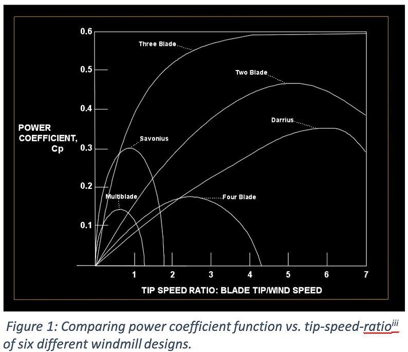
Governments and project developers have recognized a renewed interest in integrating wind-power technology into contemporary building design. [i] Critical issues with horizontal windmill technologies include start-up behaviors. [ii] Other critical issues with windmill technologies are found in the dynamics of air flow at low tip-speed ratios (TSR). This is not a factor with horizontal type turbines, as the TSR is generally 1, [iii] for all horizontal windmills (Figure 1). Airflow behavior, however, generally causes efficiency issues in the airfoil wake that complicate the use of VAWT's for small-scale power production. [iv], [v], [vi] These complications arise from diminished maximum predicted efficiency as compared to other turbine designs. In commercial applications, the Betz Limit for wind turbines is 59.3%.[vii] However, with conventional VWAT or Savonius turbines, the practical upper limit for wind energy conversion is ~30% (Figure 1).
These issues plague VAWT windmill market penetration, as they generally do not reach satisfactory power output in stand-alone capacity. Mill placement locations are also critical for market penetration.
Former studies have shown that for optimal output capacities, a region suitable for commercial windmill placement must experience on average between 20 and 30 mph wind speed. [viii] One attempt to circumvent this problem with is a patent prototype that uses helium balloon assist and two jet propulsion engines to raise a windmill to altitudes where wind speeds reach average optimal ratings consistently. [ix] Other current studies in windmill technology focus on building many windmills in “wind-field” fashion atop large area roofs. This may prove to generate a great deal of future power. [x]
Further studies to advance wind technology involve attempts to reduce friction losses between bearing and rotor shafts. [xi] Magnetic levitation is currently being studied as a novel approach. [xii] Ring magnets, however, experience a magnetic field decomposition overtime that begins at the outer edges of the flux field. This magnetic field decomposition results in eventual judder at the outer-diameters of a horizontal windmill, a wobble effect that over time reduces overall efficiencies. To reduce these judder effects, and stave magnetic field decomposition at the outer edges of ring magnets, novel approaches are being taken in configuration of permanent magnets for magnetic levitation, inside mag-lev housings. [xii], [ix]
Theory
VWAT windmill power output is effected by the overall airfoil dynamics and the effect of eddy currents in the wake of the turbine. In this study, Energy Con focused on increasing VAWT power coefficient at low wind speed. To necessitate a better design, we attempted to build a better wind trap by using cutting edge novel rotor-stator configurations, and wiring in our VAWT, along with mag-lev and coupling magnetic fields. To reinvent the wheel is difficult, as its functions are primal. We believe nevertheless, that by relieving friction stress and mechanical losses between our VAWT's assembly and housing, and by relieving heat (phonon) build-up in coil and stator assemblies, our novel concept may have reinvented the way we look at VWAT windmill technology. With Energy Con's added magnetic areas between rotor and stator, and forced-air turbine assist through rooftop vent assemblies, it allowed our horizontal windmill to reach near the Betz Limit for a three blade horizontal axis wind turbine. If this is the case, this VWAT windmill is the next step to energy security.
No matter what novel approach is taken to improve VWAT windmill efficiencies, the overall wind harness to electricity movement is pushing toward harnessing low-speed wind potential by increasing the power coefficient.
The power coefficient of a turbine is its output in watts divided by wind power. [xiv], [xv] (Equation 1).
Wind power is proportional to the air density multiplied by swept area, times wind velocity cubed. [vi], [xvi] (Equation 2)
Power in a wind turbine is a product of voltage and amperes. Voltage in generators is defined by Faraday’s law. [xvii] (Equation 3)
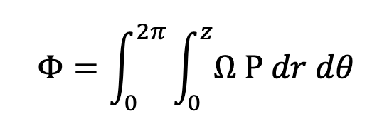
The SI unit of magnetic flux is the Weber. (Equation 4) This is a first-order integral which involves integrating the permeability of the active magnetic field’s outer and inner radius, its area, and the flux density of the magnet, then multiplying by the derivative of the angle in the active magnetic field. [xviii] Counting magnetic lines to ascertain flux density is tedious. In conventional technology, a magnetometer is sufficient to ascertain magentic flux. [xvi] Many scientific analyses have been conducted to describe magnetic flux. [xix], [xx] In this paper, we conducted our theoretical analyses using the data as ascertained by Arnold Magnetic Technologies, [xix] and Alliance LLC. [xx]
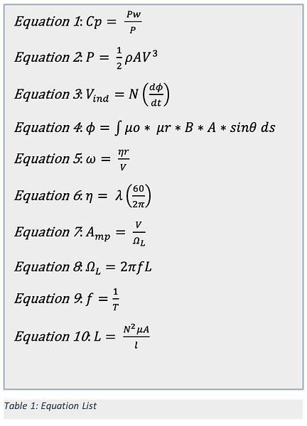
When scientists know the number of turns in the coils and the flux density of the coils inductive field, induced voltage is ascertained by calculating the amount of time it takes the magnetic flux of the magnet on the rotor to pass through the cutting field of the coil on the stator. Conventional analyses begins with Hertz, (Equation 5) and is then converted to RPM. [xix] (Equation 6)
Amperes in a generator are defined by Ohm’s law, (Equation 7). To define the resistance of an inductor, and the eventual ampere output we used inductive reactance. [xv] (Equation 8) In the design below, inductive reactance is proportional to frequency, (Equation 9) and Henry, [xv] (Equation 10).
Since the copper coils are so small, copper resistances are assumed arbitrarily negligible, and we gave copper resistances a value of 0, and used inductive reactance as resistivity.
Total inductive reactance is ascertained by the sum of each phase’s inductance in series. [xv]
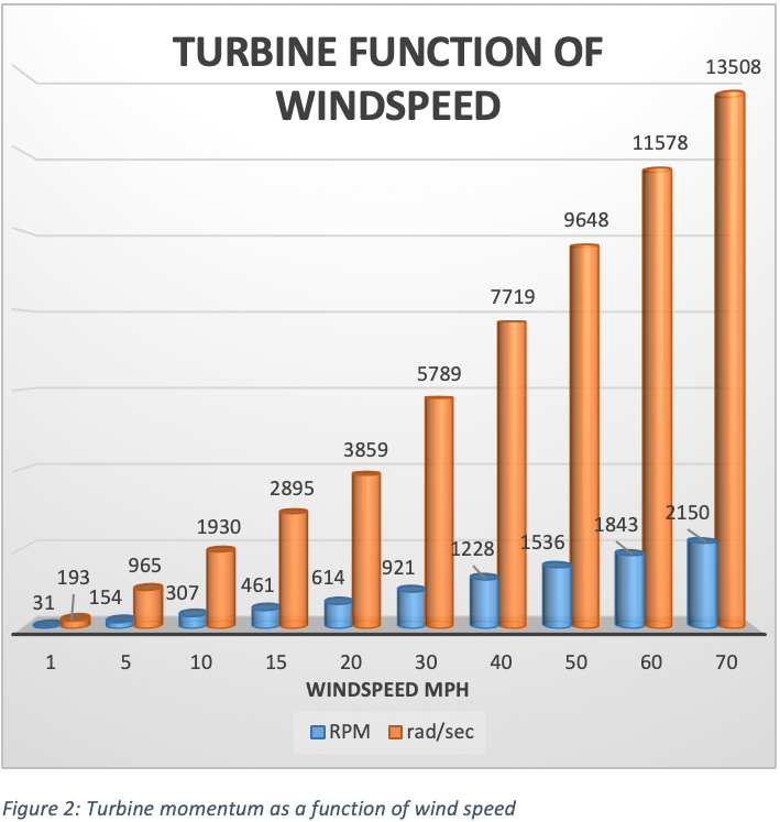
The rotor has a diameter of (proprietary) inches, and the stator (proprietary) inches. However, the actual configuration of the energy conversion and harnessing components have a diameter of (proprietary)”. With this, 2p*5.47”, the rotor completes a turn for energy conversion and harvest every 34.38”, or it travels 0.873 meters in one period. Using engineering data, we divided wind-speed in meters per second by the radius of the rotor. After attaining revolution per minute, to convert into radian per second is conventional. This is accomplished by multiplying the former quotient to the quotient of 60 and 2p. (Figure 2).
Using flux density for Neodymium N40 permanent magnets, [xvii], [xviii] we multiplied the number of turns in each coil by radian per second, by flux density, by the cross sectional area of a single coil’s cutting field. This provided us with individual output voltage for each coil at a designated wind speed. Because our stator configuration is three phase, each phase pulses (proprietary number) degrees out; the (proprietary number of) magnets in configuration on the rotor, separated at (proprietary information) degrees, allows three coils to induce voltage simultaneously. Thus, the physical effect triples single coil output.
Completing a revolution every 0.873 m, the rotor induces voltage in all three coils nine different times. This effectively increases the output of the VWAT nine-fold. This appears true at a variety of different wind speeds.
Prior literature concerning wind-form power harness states that the design of a windmill will cause it to act differently given different wind speeds. Each design has its own unique optimal function and output performance. With this understanding each design will have an optimal wind speed. [vii] At other wind speeds the turbine will experience pulsing power moments. This could cause stall, and other unwanted behaviors such as judder, or vibration in the housing. These behaviors will affect efficiency in overall performance, and in the overall life time of the windmill.
The faster a turbine spins, the more voltage it is capable of inducing. This is directly correlated to how much wind energy the turbine is capable of capturing, and how fast the wind is traveling.
Multiplying the power output of three coils in our VWAT, by the nine times each phase will induce during a period, (revolution) and adding variable wind speed to the equation, it was ascertained what wind speed our particular design will like the best. These figures do not include the Betz limit for turbines which is typically 59.3% for a commercial turbine, and negligible at ~30% for a Savonius type turbine as is our design. [iii]
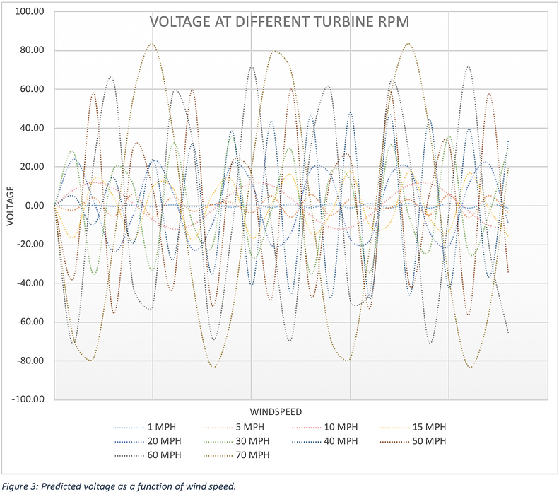
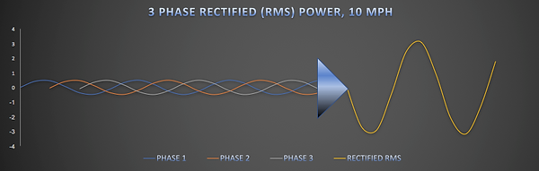
As can clearly be noted by the fluid sinusoidal wave for voltage at 10 mph, (Figure 3) the design of our Savonius VWAT is consistent with current design efforts to get optimal output of a wind turbine. [vii] The wave is still nearly optimal at 20 mph; however, it begins deteriorating in uniformity somewhere between ~20 and ~30 mph.
With voltage defined, we still had to determine resistance to attain the output in ampere, and determine power output at a given wind speed. In doing this we used inductive reactance. [xv] This is the number of turns in the coil squared, multiplied by the permeability of copper, and the cross-sectional area of the coil core, divided by the length of the coil. Because we initially intended to connect the coils in series and each coil series is (proprietary information) degrees out of phase with one another, current should not change. [xv]
As the turbine spins faster, its current and voltage increases. However, the faster the turbine pushes voltage into the coils, the more the coils react, and push the voltage back toward the path of inductance. This is inductive reactance. Therefore, as the coil induces a voltage, it also induces a reactance. This reactance is proportional to the induced voltage, and is the basis for current stability in a series connection.
The unit of inductive reactance for a turbine is the Henry (L). (Equation 11) Each phase being wired in series, three of the (proprietary information) coils induce voltage simultaneously, effectively provides more coils in the inductant moments. (Equation 12) Instead of 50 turns, our output is inducing through 150 turns, (Table 2) while effectively removing a great deal of the inductive reactance.
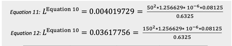

Using Ohm’s Law, volts divided by Henrys equals amperes. Once the assured series connection was ascertained by understanding the current did not change through a range of wind speeds; the product of amperes and volts provides power measured in watts of output per phase. (Table )
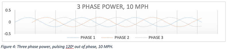
Because each phase in the stator is ( ) degrees apart, output power will activate in streams. (Figure 4)
With the data appearing correct, and the engineering rule, or specifications within correct tolerance, the next step was determining rectified power. (Figure 5)

At this point the description of output power is based on ECMD Energy's VWAT capturing and converting wind power. The upper limit of the theoretical analyses may provide somewhat of a false impression. No turbine can harness all the potential energy in the wind. If this were possible, the turbine itself would stop the wind completely. Because the wind passes through the turbine, and flows at a diminished rate out the backside, there is a limit to the amount of energy the wind can provide given present technology. This is known as the Betz percentage. It is the maximum amount of wind energy that current wind technology can convert to usable power. This limit is 59.3%. [vii] It is what all commercial turbines attempt to achieve. The vertical mill or Savonius, such as our VWAT experiences even more limits to the amount of power it can harness. One major setback in our design, is that only 50% of its diameter, front face, can catch the wind. The other 50% of the frontal area, or the area of the turbine the wind sees, works against the wind. For the 50% of the frontal area of the Savonius that captures wind energy, it too faces setbacks in efficiency, eddy currents, wind direction, velocity, lift, drag potential, etc . . . . This isn’t even putting the correct context of heat buildup in the stator and coil assemblies into perspective. Everything told, a Savonius such as our VWAT may experience multi-variable losses in overall efficiencies. That is why scientists believes that given current technology, on a stand-alone basis a Savonius turbine will not be economical. However, coupling novel technology as is included in our VWAT, and several VWAT together, it may be feasible economically to install our systems. [x]
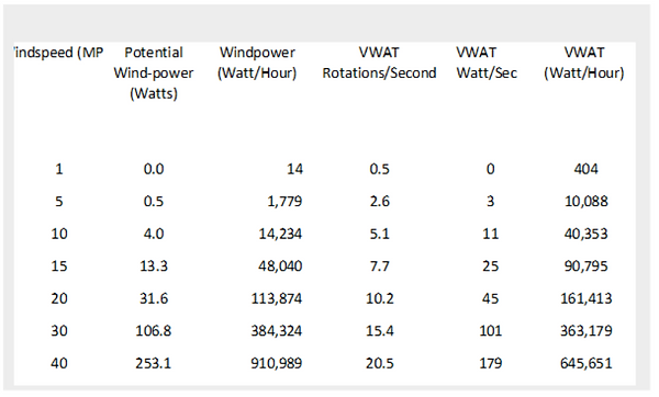
With present technology, researchers generally understand that a Savonius turbine’s maximum efficiency is somewhere around 30%. (Figure 1) Engineering data shows that the overall energy contained in wind currents moving at 10 MPH, is 4 Watts. (Table 3)
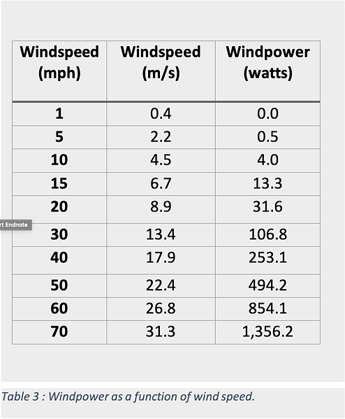
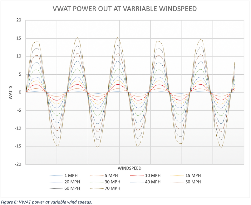
That would put output for a typical Savonius windmill in a wind of 10 MPH, at 1.2 Watts. With our analyses of ECMD Energy's mag-lev design herein, in a wind of 10 MPH, we've recorded an output at 2.2 Watts and better, per revolution, (period) giving it a 55% conversion rate. A percentage of wind-to-electricity that has never been recorded before for this type of vertical design, and very near the Betz Limit for any conventional wind-energy turbine. (Figure 6)
As wind speed increases, however, it appears the mag-lev VWAT’s efficiency decreases, at 15 MPH 25%, 20 MPH 14%, etc.
With the efficiencies described above, the efficiencies for Energy Con's VWAT on a Watt-hour basis also decrease, as wind speed increases. (Table 6)
Even though the efficiency decreases, the power output in Watts increases. To maintain efficiencies it would be desirable to keep the turbine turning as if the wind speed were 10 MPH, at all times.
CONSTRUCTION OF THE PROTOTYPE
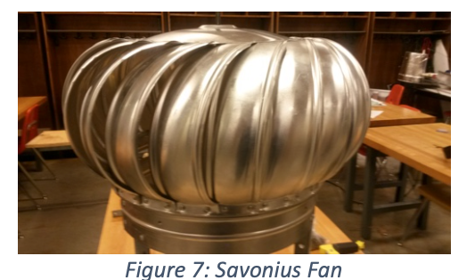
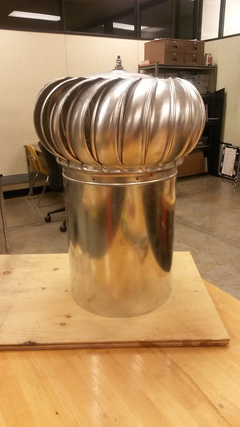
The rooftop vent cap turbine or 'Savonius Fan' itself is conventional. They are used wide-scale for vent-cap fixtures worldwide. We decided upon this design, because it is “drop-in-replacement” for many existing building vent structures. The added appeal of “drop-in-replacement” also adds aesthetic value. Wide scale application of the simple Savonius fan design is already in use.
Because vertical access wind turbines typically experience slow start up in low wind environments, we ascertained that using a stationary stator inserted as part of the building's venting conduit, that normally sits beneath a rotating Savonius fan on rooftops, was our best option. (Figure 7: Savonius Fan)
Because the stator assembly contains the copper coils this kept as much weight off the actual moving components as possible, and aided in slow wind speed start up.
Once we decide on design characteristics, we began retrofitting the existing building's ventilation system that one would normally see sitting atop large flattop buildings and warehouses. We inserted rotor magnets in a fashion to sit snug inside the bottom opening of the vent cap turbine, or moving part of the mill.
In our Savonius housing, we installed (proprietary number), N40, Neodymium bar magnets each with a 0.5” width, and a 3” length. Each magnet is affixed at ( ) degrees with poles alternating north, south. This enables 3 of the magnets, each positive or negative, to be directly above three coils in the stator at all times during the turbine’s rotation. (All magnets ¼” thick)
Once the rotor was ready, we moved on to the modification of what is normally the end of a building's venting system, or the neck of the system where the vent cap turbine in normally affixed.
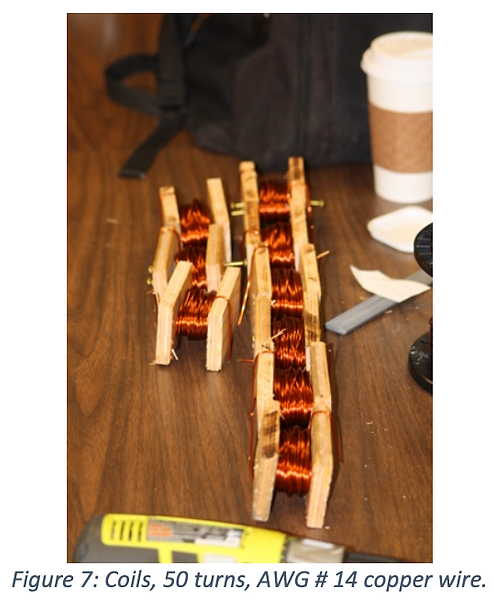
The stator is multi-variable. It contains (proprietary number) coils with 50 turns each. (Figure 7: Coils)
Phases can be wired from one to nine phase, series, or parallel. The design is a proto-type, and during the construction process Energy Con ascertained that it would benefit our understanding of Mag-Lev VWAT if the stator were constructed in a way that would let EnconDes team members manipulate wiring context. This allowed us to work around conventional drag and other malformation in VWAT material mechanics. Stator mock-up with coils at (proprietary number) degrees, waiting for (proprietary) and thermal, phonon, dissipation compound is viewed in Figure 8.
Figure 8 is Proprietary Information
Insuring that the novel design would be able to set inside roof top vents, and not impede air vented from structures, instead of using a solid base, or air blocking stator design, the stator contains open air coil cores, and open air spaces between each coil. This air-cooled design also serves as a direct conduit for thermal dissipation.
Instead of retrofitting the turbine with a brake, so that phonon build up does not damage coil components at high wind speeds, or depreciate efficiencies. We used (propriatary) capable of withstanding ( ) degrees F, surrounded with a (proprietary) for further phonon convection, to channel heat away from the coils to the air cooled open vents.
The stator/rotor are separated by an air gap. The vent cap, turbine, setting atop the stator are the actual wind harnessing components. Without the conventional rotating shaft connecting torque to the gear box, the design allows for decreased friction as compared to a gearbox design.
To further alleviate friction between the rotor and stator, we’ve installed novel magnetic levitation.
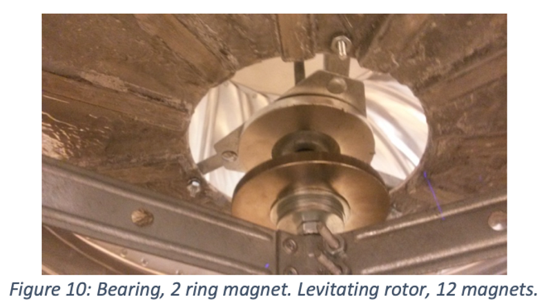
The rotor floats over the stator at a nominal ~0.5" distance, as calculated by the novel equation below. This is achieved by using two N40 Neodymium ring magnets with a 1.5” inner diameter, and 3” outer diameter. To stave potential judder at the outer edges, a stationary all-thread bolt sits vertical, and holds the rotor/stator together. This bolt does not revolve in the housings. The only thing that moves in the configuration is the actual vent cap, or turbine atop the mag-lev bearing. Helping to reduce friction and slow speed start-up that plagues other Savonious mills.
One facet of Energy Con's novel design is that the rotor can either float over the active zone of the magnetically levitated bearings, or the rotor can be wrenched down into the opposing forces. This gives the rotor a spring effect. It is unclear as to the overall ramifications of the magnetic spring. But we hypothesize that as the magnetic fields are wrenched further down upon one another, the levitating spring will hamper start up and rotational capacities. We believe this will decrease efficiency in the overall design. Thus we have used novel calculations to determine the best distance between levitation magnets, the "sweet spot," or the exact distance between ring magnets, for optimum fluidity of clashing magnetic fields.
In contemporary mathematics, in order to calculate the volume of a sphere such as the toroidal sphere of a magnetic field, Integral Calculus is required, (Note: r is a constant.) [xxii], [xxiii]
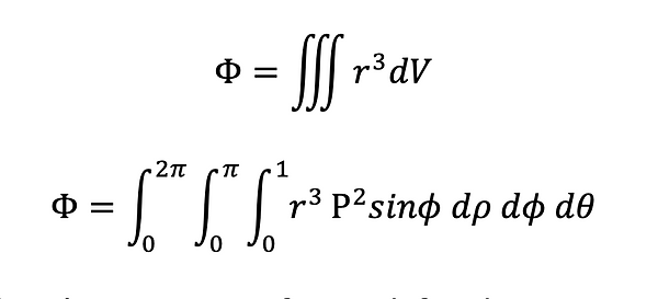
The flux at the sphere’s Gaussian surface is defined. [xxiv]

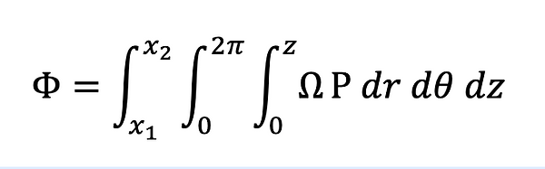
Magnetic fields are usually not perfect spheres. Multiple variable or Integral Calculus allows the use of small slices of the Gaussian paraboloid. [xxii] We add these slices together to obtain overall volume of the magnetic fields (z; x2+y2+z2= Ω; x1 and x2; are constants.)
This is only a cross section of the toroidal sphere, a paraboloid in two-dimensional space: width and height. In order to get the desired results in all three dimensions, the length of the cross section must be incorporated into the second order, which again produces a third order integral.
In order to obtain overall volume of the magnetic field, each of the inner slices are summed together. The number of individual parts of the whole depend upon overall shape of the toroidal cross section, these are paraboloid. This identifies that it could become a very complicated, extensive and tedious list of equations, just to define the Gaussian sphere of a single magnetic field.
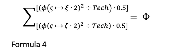
It is not necessary, however, to use an integral to define magnet flux, [16]. Single order integrals are in themselves tedious. They are the inverse of the derivative. In attempt to better define levitation Gaussian boundaries, Energy Con used novel mathematics. Much like the integral is the inverse of the derivative, the novel concept “Tech” is introduced as an inverse of “Pi”. As “Pi” is 3.14159265359 . . . “Tech” is © 1.9108281.(Techtronics, 2021-Edifycation. 2003. TXu001169740. ) Unlike Pi, Tech may not be infinite. Using “Tech”, it is possible to define Gaussian surfaces with a novel approach, without the use of an infinite number that leave for a +/- varriance. This concept is only available on stand-alone basis if the Gaussian surface of the Planck-Field being analyzed is a sphere and symmetrical.
In this case they are. (See the orange Box labeled Generator above for a symbol key)
In 3D space the two conventional circular magnets are stacked one on bottom, one on top, centered over one another. Polarities of Gaussian surfaces are in positive opposition. Which forces the magnetic fields apart. They release their combined theory affect just above the Gaussian surface or wave boundary.
Each of the two Gausssian units individually divided by “Tech” produces two separate magnetic spheres, each containing its own quantifiable Plank Flux.
Mechanically wrenching these fields together, and restricting the systems’ environment combines the two fields together. Combining units of magnetomotive force that double flux density of a single magnet, thus it appears to have doubled this system’s potential energy output. Which is a possible explanation for the systems near Betz limit efficiency. The most fascinating aspect of this novel design is that the system appears to be generating voltage while the Savonius turbine remains stationary. This is witnessed in the second video below.
CONCLUSION
All told the current cost of Energy Con's prototype windmill is ~$500. These costs were mostly apprised through the purchase of high heat ceramic dielectric and the thermal dissipation compound. The second highest cost was incurred at the price of magnets. It is ascertained that these overall costs could be decreased upon purchase of larger quantities of the dielectric and thermal dissipating compound. Prices for a a gallon of these compounds are $250 as opposed to $208 for two quarts. It would also greatly decrease capital costs if large orders of magnets were attained. ECMD surmises that the turbine vent cap retrofit costs for conversion to the energy harvest apparatus, and roof-top structure to interior or grid tie power, would be cut by at least 50% or more, if two of the devices were retrofitted simultaneously. This means two or more turbines could be built for the price of one.
Open core stator as shown above, (proprietary) allows for more space to insert coils inside the stator’s heat radiative design. This should allow thermal dissipation and still enable the stator to maintain phonon transfer if coil windings were doubled. Theoretically doubling the windings will double the power output of the current prototype, at minimal increases in construction costs.
Doubling the number of windings in the coils would also double the amount of inductive reactance thus adding more heat emissions from the operating system. It is unknown at this time how much heat Energy Con's novel VWAT emits as a byproduct of power generation. With the air cooled open stator-coil design vent assist aids in cooling.
More data is need to ascertain overall head production, return on investment, and efficiencies. This data includes a study to gather among other data:
1. Information to ascertain if the system is somehow gathering energy by converting the Gaussian fields. As was shown in the second video above, there is a fluctuation of voltage, and it appears energy is being converted while the vent-fan rotor remains stationary. This may be a fluke caused by a malfunctioning multimeter or it may be that even though the rotor appears stationary to the naked eye the magnetic fields in their compressed state are vibrating microscopically, forcing the rotor to move back and forth ever so slightly like a crystal in a timepiece. The hypothesis here is that if we could lower the temperature of a substance to zero-Kelvin, there are still aspects that would allow the lattice of this substance to vibrate. Shedding a new light on the First Law of Thermodynamics. This would not necessarily rearrange our understanding of Thermodynamics, it would only prove to enforce the belief that substances at zero-Kelvin still maintain electron movement.
2. Install electronic brakes to allow for slow wind/vent/exhaust speed start up, and to keep turbine from over rotating and losing efficiency in high wind/vent/exhaust speed environments. The brake is proposed to be affixed to the outer hem of the stator, and much like a train wheel running on a single track, it will act to inhibit judder and impede over-rotation. Another possible braking system could be attained by wrenching the magnetic fields further down upon one another. As it is a stronger more robust all-thread bolt needs to be installed, because the weak metal of the current all-thread allows the fan-rotor to wobble. As can be heard in the first video above, the hem of the turbine is clacking at times on the vent conduit housing due to force applied. It is however hypothesized that the wheel-brake proposed above would negate this need.
3. Study the effect of vent exhaust energy that normally escapes a building. An affect that would increase output capacity of this design. This energy was not added as a part of this study. It is also hypothesized that adding vent fins to the inside of Energy Con's VWAT would novelly address the issue of surface area, and the ECMD's VWAT deign would be able to function at better than 50%, because the wind would be better assisted by the buildings exhausts, enlarging the surface area all the air convective currents see as they approach our VWAT.
4. Add the novel approach of magnetic propulsion, (See the orange 'Generator' block above) which may turn the turbine upon input of clashing magnetic fields without the need of wind/vent/exhaust forces.
Bibliography
[i] Ashraf A. ELMokadem, Naglaa, A. Megahed, Dina. S. Noaman. (2016.) Systematic framework for the efficient integration of wind technologies into buildings. Volume 5, Issue 1, March 2016, pp. 1-14
[ii] Untaroiu, A. Wood, H.G. Allaire, P.E. Ribando, R.J. (2011.) Investigation of self-starting capability of vertical axis wind turbines using a computational fluid dynamics approach. J. So. Energy Eng. 133.
[iii] Ragheb, M. Optimal rotor tip speed ratio, 2014. [Figure 3: indicating Power Coefficient at Function of Tip-Speed-Ratio] Web, Accessed, December 10, 2016.
[iv] South, P. Rangi, R.S. (1975). An experimental investigation of a 12ft. Diameter high speed vertical-axis wind turbine. National research council of Canada, Ottawa (1975).
[v] K. Fukudome, M. Watanabe, A. Lida, A. Mizuno. 2005. Separation control of high angle of attack airfoil for vertical axis wind turbines. Proceedings of the 6th KSME-JSME thermal and fluids engineering conference (2005).
[vi] Visbal, M.R. (1990.) Dynamic stall of constant-rate pitching airfoil. AIAA J. Aircr, 27. (1990), pp. 400-407.
[vii] Piggott, H. (2011). Wind power workshop: building your own wind turbine. Aberystwyth, United Kingdom. Cambrian Printers.
[viii] Jha, A.R. (2011.) Wind turbine technology. Taylor and Francis Group, LLC, CRC Press. Pg. 51. ISBN: 978-1-4398-1506-9
[ix] Mohamed, Hassan Nazar. (2013). High Altitude maglev vertical-axis wind turbine system (ham-vwat). PatentScope. Pub. No. WO/2013/189503.
[x] Chonmapat, T. Sermsri, N. (2015.) The application of roof ventilator for electricity generation. Procedia – Social and Behaviroal Sciences. 7th World conference on educational sciences. Volume 197, July 2015, pp. 1690 – 1606.
[xi] Korzen, V. (2012). Magnetically levitated linear barrel generator. Google patents. Pub. No. US8198748 B1.
[xii] Kumbernuss, J. Jian, C. Wang, JH. Yang, HX. Fu, WN. A novel magnetic levitated bearing system for Vertical Axis Wind Turbines (VAWT). APPLIED ENERGY. Volume: 90 Issue: 1 Pages: 148-153 Special Issue.
[xiii] Rodriguez, E. Sotelo, G.G. de Oliveira, J.G. de Santiago, Juan. Rossander, M. Stephan. R.M. (2016). Designing, simulations and experiments of a passive permanent magnet bearing. International Journal of Applied Electromagnetics and Mechanics, 51 (2016) 131-149.
[xiv] Korprasertsak, N, Leephakpreeda, T. (2016.) Analysis and optimal design of wind boosters for Vertical Axis Wind Turbines at low wind speed. Journal of Wind Engineering and industrial aerodynamics. Volume 159, pp. 9-18.
[xv] MacPhee, D.W. Beyene, A. (2016.) Fluid—structure interaction analysis of a morphing vertical axis wind turbine. Journal of fluids and structures. Volume 60, January 2016, pp. 143-159.
[xvi] Quan, P. Leephakpreeda, A. (2015.) Assessment of wind energy potential for selecting wind turbines: an application to Thailand. Sustainable energy technology Assessments., Vo. 11. September(2015), pp. 17-26.
[xvii] Floyd, T.L. 2010. Principles of Electric Circuits, conventional current version. 9th ed. Prentice Hall, Upper Saddle River, NJ.
[xviii] Preeti, Jain, (2016) Magnetometers, Engineers garage: inspiring creations. Retrieved from: http://www.engineersgarage.com/articles/magnetometer
[xix] Arnold Magnetics, (2016). Neodymium-Iron-Boron Magnets. Web. Retrieved from: http://www.arnoldmagnetics.com/en-us/Products/Neodymium-Magnets.
[xx] Alliance LLC, Magnetic guide & tutorial. Web retrieved from: http://www.allianceorg.com/pdfs/Magnet_Tutorial_v85_1.pdf.
[xxi] Larin, P., Paraschivoiu, M. (2016). CFD based synergistic analysis of wind turbines for roof mounted integration. Journal of Wind Engineering and Industrial Aerodynamics. Vol. 156, pp. 1-13. September 2016. Http://dx.doi.org/10.1016/j.jweia. 2016.06.007
[xxii] Tzeng, Y. (2013). Triple integrals in Cylindrical or Spherical Coordinates. Harvard University. Cambridge. 2013. http://math.harvard.edu/~ytzeng/worksheet/1104_sol.pdf
[xxiii] OSU. 1996. Tripple integrals in cylindrical and spherical coordinates. Department of Mathematics, Oregon State University. © 1996.
[xxiv] Guetta, D. 2009. Flux, Surface Integrals & Gauss’ Law. A guid for the perplexed. Massachusetts Institute of Technology, 2009. http://web.mit.edu/8.02t/www/materials/StudyGuide/Flux.pdf

Let’s Work Together
Get in touch so we can start working together.